
Audio PCBA powers amplifiers, speakers, and audio interfaces with low-noise layout and clean power. Kilandu builds Bluetooth speakers, amplifiers, and audio control boards with 100% functional test for consumer and professional audio brands.
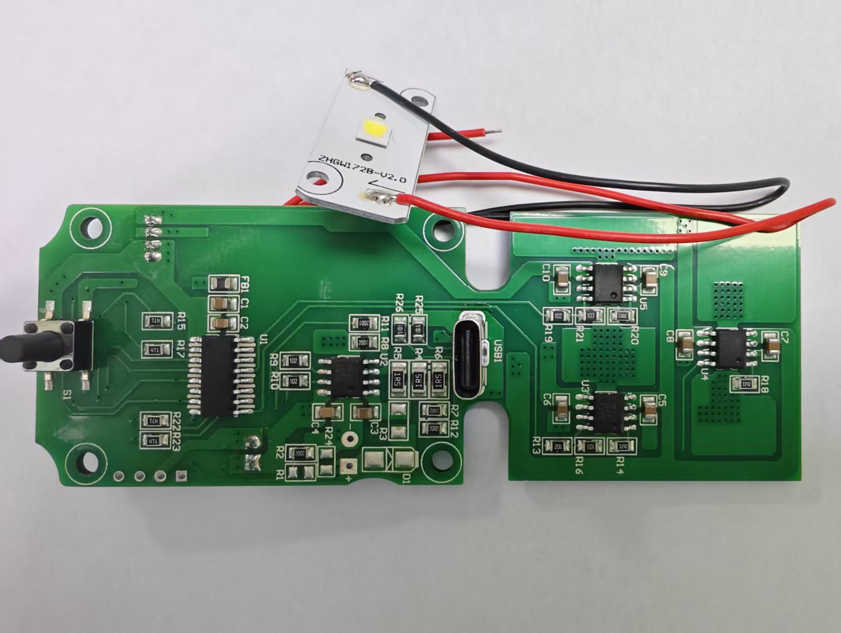
- Class D / Class AB amplifier boards
- Bluetooth & smart speaker PCBA
- Audio control and power interface boards
- Low-noise layout with clean power and grounding
- Turnkey component sourcing
Capability
What Kilandu can build, test and ship for this product family.
| Parameter | Capability |
|---|---|
| Types | amplifier / speaker / interface |
| Topology | Class D / AB |
| Noise | low-noise layout |
| Test | 100% audio functional test |
| Components | BGA / QFN, codecs |
| Lead time | 2-5 weeks |
Applications
Where these boards are used by our customers.
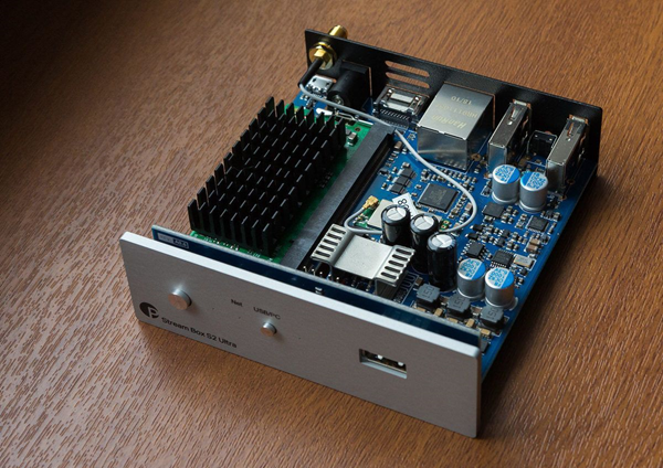
Bluetooth / smart speakers
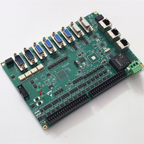
Speaker boards with wireless modules, antenna layout and acoustic-friendly grounding.
Amplifiers & audio control boards
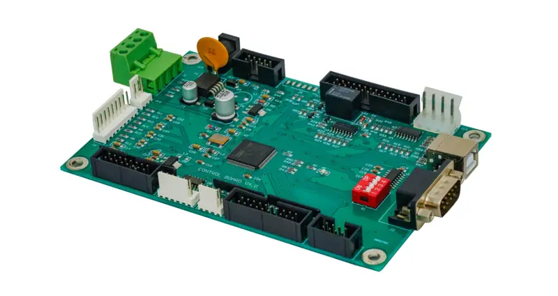
Class D / AB amplifier boards with thermal design and pop-free start-up.
Professional audio interfaces
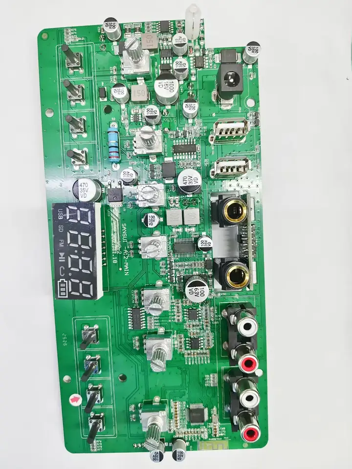
Balanced I/O, DAC/ADC and power-interface boards for studio and stage gear.
Automotive audio modules
Amplifier and audio-control boards for in-car entertainment and head units.
How we build it
From solder paste to tested board, inside our own factory in Shenzhen.
SMT assembly
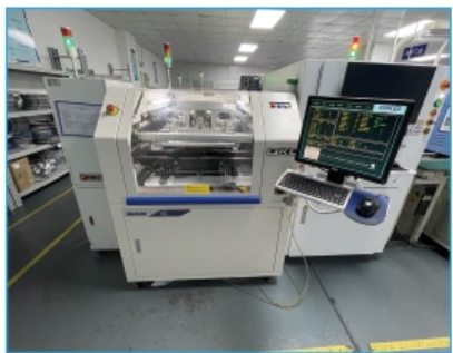
01005 chips up to BGA/QFN placed on high-speed lines and reflowed per IPC-A-610.
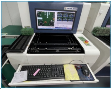
AOI + X-ray
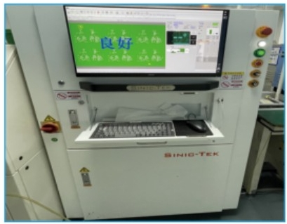
Automated optical inspection on every board, with X-ray for BGA and hidden joints.
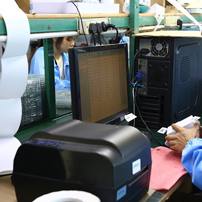
ICT & functional test
In-circuit and functional test against your test specification, per-lot traceable.
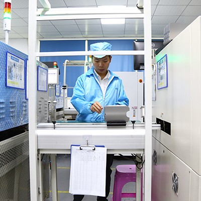
Audio performance test
100% audio functional test before shipment, including noise and channel checks.
What audio performance depends on at the board level
An audio board is judged by numbers that are decided mostly by layout and grounding rather than by the parts list. Total harmonic distortion (THD) and signal-to-noise ratio (SNR) are set by the analogue front end: how the reference and the analogue supply are decoupled, where the return currents flow, and how far the sensitive input sits from the switching supplies and the digital section. Frequency response depends on the passive network around the amplifier and on the parasitics the layout adds to it. On a Class D amplifier the output stage switches at high frequency, so the layout of the output filter, the loop area of the switching path and the placement of the decoupling decide both the distortion and the radiated EMI that has to be contained.
Class D and Class AB are assembled differently
The two amplifier families put different demands on the board. A Class AB stage is a low-noise, mostly analogue problem: star grounding at the input, a quiet analogue supply, and separation between the input ground and the speaker return. A Class D stage is a switching problem: tight loops, a filter inductor placed close to the output pins, and thermal copper under the output devices because the stage is more efficient but still dissipates at high output power. Boards that carry both - a Class D output with a Class AB headphone stage, or a digital section alongside analogue - are laid out with the analogue and switching areas separated, and the assembly process is set so that separation is not undermined by stray flux, coating or solder bridging.
Shielding, MEMS microphones and digital audio
Where a board carries a wireless module, a switch-mode supply or a Class D output next to sensitive analogue circuitry, an EMI shield or screen can be added over the noisy section, and the shield frame is fitted and inspected as part of the assembly rather than treated as a mechanical extra. Boards that include MEMS microphones, an audio codec or a DSP bring their own constraints: acoustic ports have to stay clear of coating and flux, the codec clock and data lines are kept away from the analogue input, and jitter on a digital audio clock is a layout and termination question rather than a component choice. Crosstalk between channels - and the audible noise floor that results from it - is controlled by trace separation, by ground stitching between channels and by keeping the high-current speaker returns out of the small-signal ground.
How an audio board is verified
In-process inspection covers paste volume with SPI, placement and visible joints with AOI, and the joints under modules and hidden packages with X-ray; electrical test covers in-circuit test and a functional test. Where the product has an audio specification, the functional test is extended to cover it: output power at a defined load, gain and channel balance, and a measurement check of THD, SNR and frequency response against the customer's limits. Every board is functionally tested, and ageing is applied where the product warrants it. Prototype builds typically take 5-8 working days and production 2-5 weeks.
Boards in this family
Board types Kilandu assembles in this product family.
- Smart Bluetooth speaker PCBA – the main board of a smart speaker, with the Bluetooth radio, the audio path and the power stage on one board.
- Speaker audio PCBA – the amplification and signal-processing board behind a loudspeaker, soundbar or powered monitor.
- PCBA board for audio device control and power interface – the control and power-interface board of an audio device, where clean power and connector ESD care lead the layout.
Frequently Asked Questions
Quick answers to what buyers ask us most about this product family.
What audio boards do you assemble?
Bluetooth speakers, amplifiers, audio control, and interface boards with low-noise layout.
Do you test audio performance?
Yes - 100% functional/audio test per board before shipment.
Can you handle Bluetooth/Wi-Fi audio modules?
Yes - SMT assembly of Bluetooth/Wi-Fi SoC modules with antenna tuning support.
How do you deal with noise and grounding on audio boards?
Noise performance is decided mostly by layout, so we raise it at DFM stage: separation of analogue and digital ground returns, placement of decoupling close to the device, and routing of switching nodes away from sensitive input traces. Where a stack-up is supplied we assemble to it rather than substituting.
Do you support mixed-technology audio boards?
Yes. Audio products commonly mix fine-pitch SMT with through-hole connectors, terminal blocks and large electrolytic capacitors. Our DIP lines handle wave and selective soldering alongside hand-insertion workstations.
What is the minimum order quantity and lead time?
There is no fixed minimum quantity. Typical turnkey lead time is 2 to 5 weeks, with prototype builds and repeat volume production both supported from the same process.
Send us your Gerber and BOM
We will come back with a turnkey quotation - PCB, components, assembly and test - usually within one working day.