

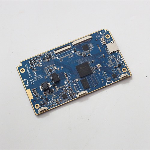
PCBA DIP plug-in processing
- DIP (Dual In-line Package) in PCBA (Printed Circuit Board Assembly) is a common packaging method for electronic components.
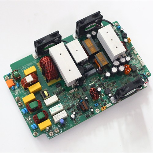
PCBA DIP processing
- PCBA DIP processing refers to the processing flow of Dual In-line Package, which is an important part of the PCBA assembly process, especially for those large or special components that cannot be installed by surface mount technology (SMT).
DIP and Through-Hole Assembly in the Same Factory as SMT
Through-hole assembly is the part of a PCBA programme that is easiest to underestimate. On a board that is mostly surface mount, the through-hole content may be a few connectors and a transformer, but those parts carry the mechanical loads, the mains voltage and the thermal mass. Treating them as a bench operation that happens after the real work is done is where a lot of quality problems begin.
How the DIP stage runs
- Programmed insertion on three automatic DIP lines for standard axial and radial parts.
- Hand-insertion workstations for connectors, odd-form parts and small quantities where programming is not justified.
- Wave soldering for boards that are predominantly through-hole, with a flux and preheat profile set for the board rather than for the machine.
- Selective soldering for mixed-technology boards, applying solder only to the joints that need it so fine-pitch surface mount parts are not exposed to a full wave.
- Cleaning where the flux chemistry requires it, followed by inspection and electrical test.
Choosing the soldering process per board
The decision between wave and selective soldering is made from the board, not from the supplier convenience. A board that is mostly through-hole with generous spacing runs faster over a wave. A board that carries 0.4 mm pitch packages on the solder side, or a connector with a plastic body that will not survive the wave, is a selective soldering job. Some programmes use both on the same panel. Because both processes run in the same building as the SMT lines, the choice does not force a second supplier into the chain.
Inspection and acceptance criteria
Through-hole joints are assessed on fill, wetting and fillet shape against the acceptance class fixed at quotation. Class 2 covers dedicated-service industrial and consumer electronics; Class 3 applies where uninterrupted service is essential, including medical, automotive and much of the power equipment built here. Automated optical inspection covers the accessible joints, X-ray covers what is hidden, and the results are recorded against the lot together with the soldering profile.
What to send for a quotation
Gerber files, the bill of materials with manufacturer part numbers, the quantity, and a note of any component that has a temperature or handling restriction. Where the board mixes fine-pitch surface mount with through-hole content, saying so at quotation stage lets us pick the soldering route before tooling is ordered rather than after. The SMT stage that usually precedes this one is described on the SMT assembly page, and the acceptance classes referenced here are set out under quality assurance.
- Factory environment

Why choose us?
Through-hole and DIP assembly covers the content that surface mount cannot carry: connectors, transformers, relays, terminal blocks and power components whose leads pass through the board. This page sets out how that stage is run alongside SMT, how the soldering route is chosen per board, and what the joints are inspected against.
Application
Each application area has its own assembly requirements. What changes from a medical instrument to a motor drive is the process, the acceptance class and the design rules that matter, and the pages below set out what is different about each one.