

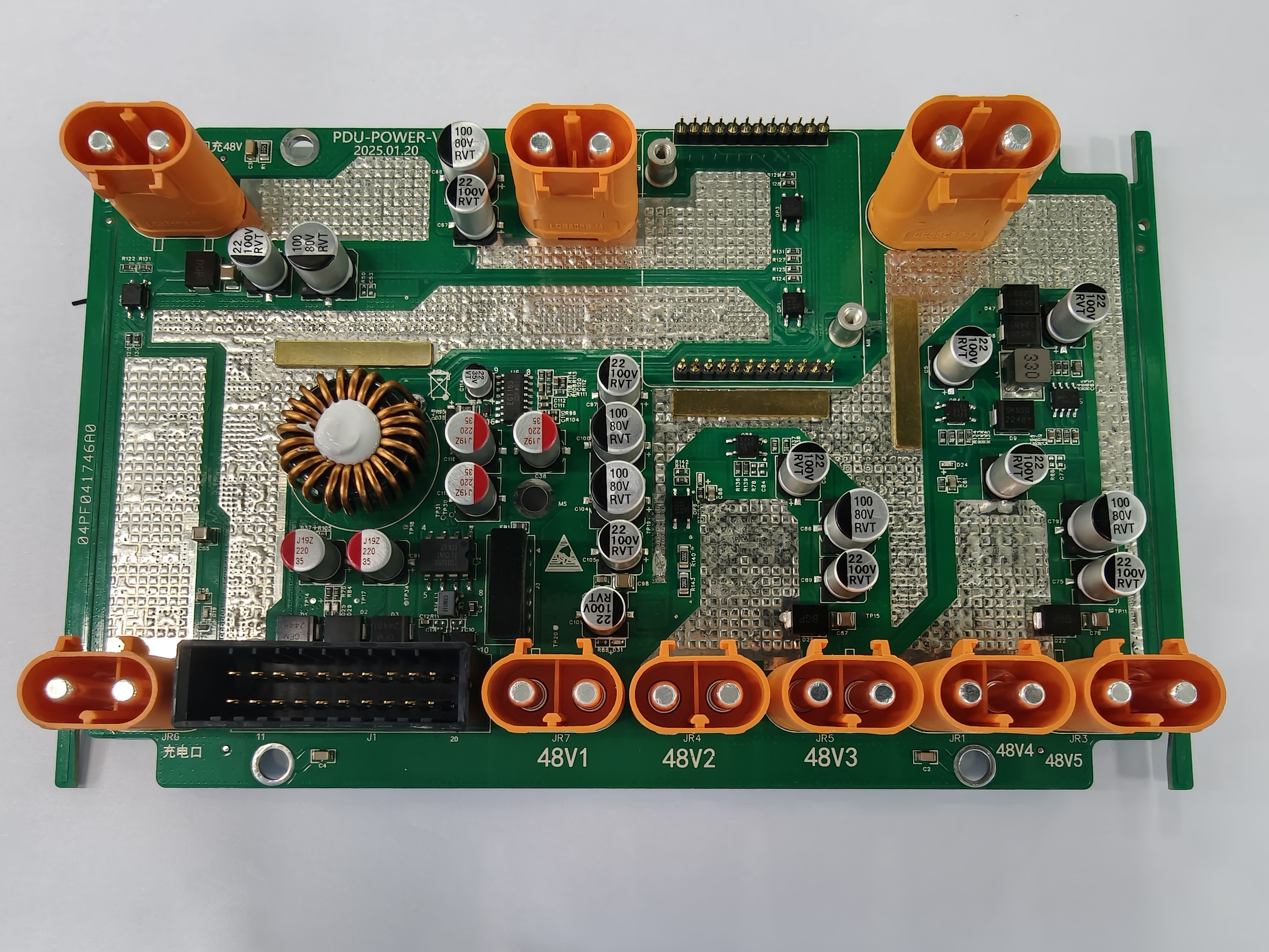
Key parameters:
Power input:
High current DC input port (orange double-pin terminal on top)
The input voltage range may be 48V~100V DC
Supports high current input, the terminal size is suitable for ≥10A current load
Control interface:
Multi-pin header interface (upper middle): used for motherboard or host computer control, such as relay triggering, CAN communication, status readback, etc.
Black multi-pin slot (lower left): may be used for external system communication or control signals (PWM, CAN, UART)
Power output:
5 independent 48V output interfaces (marked as 48V1 ~ 48V5, orange port)
The output is DC voltage, each channel can have independent control or protection functions
Indication and protection circuit:
Multiple electrolytic capacitors are used for output filtering (22μF 100V, 100μF 80V, etc.)
With multiple power MOSFETs or protection ICs (for overvoltage, short circuit or current control)
Screw holes are designed for grounding or heat sinking to enhance heat dissipation and mechanical fixation
Power drive and filter circuit:
The high-power inductor coil in the center indicates basic DC-DC voltage conversion or buffer energy storage function
SMD resistors, capacitors and ICs together constitute the basic drive/regulation logic
PCB size:
Estimated size is approximately: 170mm x 110mm
Multiple copper layers are used for current shunt and heat dissipation
Applicable scenarios:
Electric vehicle battery management system (BMS)
Industrial control power supply unit
Communication base station or server rack power supply module
High current DC distributed power system
Embedded device platform requiring multiple high-stability 48V output