

Industrial control box assembly processing
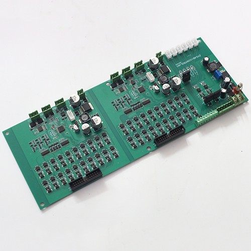
PCB board: Ensure that the quality and design of the PCB board meet the requirements of the industrial control box.
Electronic components: Prepare the required electronic components according to the BOM (Bill of Materials), including DIP plug-ins, SMT patch components, etc.
Housing and accessories: Prepare the housing, heat sink, fixing screws and other accessories of the industrial control box.
1. Preparation stage
1. Material preparation:
PCB board: Ensure that the quality and design of the PCB board meet the requirements of the industrial control box.
Electronic components: Prepare the required electronic components according to the BOM (Bill of Materials), including DIP plug-ins, SMT patch components, etc.
Shell and accessories: Prepare the shell, heat sink, fixing screws and other accessories of the industrial control box.
2. Tools and equipment:
Prepare the tools required in the assembly process, such as screwdrivers, tweezers, welding equipment, etc.
Ensure the normal operation of automation equipment such as wave soldering machines, patch machines, and reflow ovens.
3. Design and drawings:
Refer to the design drawings and process requirements to clarify the assembly steps and precautions.
II. Assembly stage
1. DIP plug-in processing:
Insert the DIP packaged electronic components into the corresponding sockets of the PCB according to the circuit design requirements.
Use wave soldering or manual soldering to ensure the welding quality.
2. SMT patch processing:
Use a patch machine to accurately mount SMT patch components to the specified position of the PCB.
Solder through a reflow oven to achieve electrical connection.
3. Shell assembly:
Install the soldered PCB into the shell of the industrial control box.
Use fixing screws or other fasteners to fix the PCB to the shell.
4. Heat dissipation:
If the industrial control box needs heat dissipation, install heat sinks or fans and other heat dissipation devices.
5. Cable connection:
Connect the cables between the industrial control box and external devices, such as power cables, data cables, etc.
3. Testing phase
1. Functional test:
Perform functional test on the assembled industrial control box to verify whether it meets the design requirements.
Check the operation of each functional module to ensure that there are no faults.
2. Performance test:
Test the performance of the industrial control box, including processing power, stability, heat dissipation performance, etc.
3. Quality inspection:
Perform a comprehensive inspection on the appearance, structure, wiring, etc. of the industrial control box to ensure that there are no defects.
- Previous:没有了
- Next:Four-port WIFI gateway PCBA