

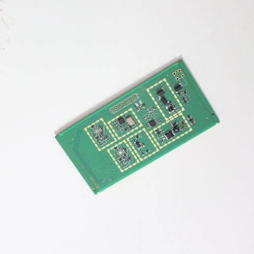
Instrumentation and Measurement PCBA
On most boards, a tolerance of a few millivolts is noise. On an instrument it may be the signal. That single difference changes what matters in assembly: cleanliness becomes a specification instead of a housekeeping matter, thermal layout becomes part of the electrical design, and the test that proves the board works has to reflect what the instrument is supposed to measure.
Where instrument boards concentrate their sensitivity
- High-impedance front ends. Surface contamination and flux residue create leakage paths that shift readings. Cleaning and ionic cleanliness control are specified rather than assumed.
- Precision and matched components. The offset and drift of a differential pair depend on both devices seeing the same temperature, so placement relative to heat sources matters as much as the parts themselves.
- References and clocks. Devices that must be stable after warm-up are placed away from regulators, power devices and anything that switches, and the thermal path through the board is considered.
- Mixed analogue and digital. Ground returns, decoupling placement and the routing of switching nodes are reviewed at design stage, since noise coupled at layout cannot be removed later.
Thermal exposure during assembly
Instrument assemblies often carry parts whose calibration can shift if they see more heat than they should: precision references, some sensors, and occasionally a battery or a display module. The reflow profile is therefore set for the whole board rather than for the largest joint on it, and where a component has a strict thermal budget that is raised before the profile is fixed rather than after a batch shows drift.
Test that reflects the instrument
Functional test is specified from the function. For an analogue input that typically means reference stability after a defined warm-up, noise floor and offset; for a multi-channel instrument it means channel-to-channel matching and crosstalk; for a transmitter it means output accuracy across the range. Where the customer has a specification, it is followed exactly. Where none exists, a procedure and fixture are developed with the first build so that later batches are measured against the same thing.
Volumes and continuity
Instrumentation rarely runs at high volume, and it rarely changes quickly. There is no fixed minimum order quantity, prototype and production builds use the same process route, and for long-running programmes the emphasis shifts to component continuity: long-lead and single-sourced parts identified at quotation, lifecycle notices tracked, and documented alternatives ready before a shortage becomes a schedule problem. Where a design mixes high-impedance analogue with switching digital, the layout questions raised at review are covered on the industrial control page; where the instrument also carries a radio link, see IoT PCBA.
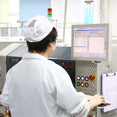
- Factory environment
What an instrument board needs from the process
Assembled boards for measurement instruments, analysers, sensors and data acquisition equipment, built in small and medium volumes with attention to analogue performance, cleanliness and calibration stability rather than to placement speed alone.
Where measurement instruments are used
Each application area has its own assembly requirements. What changes from a medical instrument to a motor drive is the process, the acceptance class and the design rules that matter, and the pages below set out what is different about each one.