

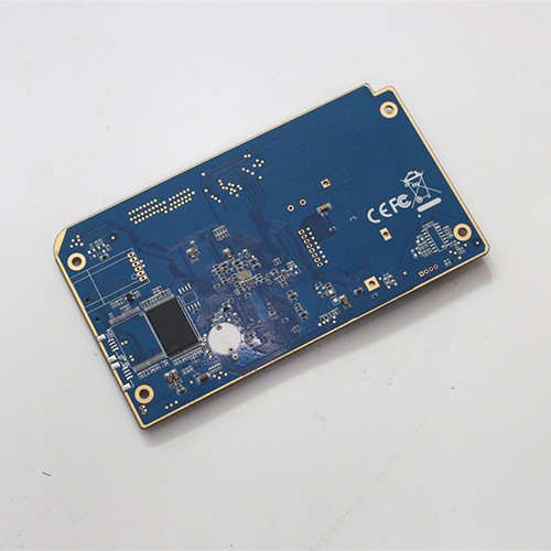
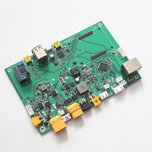
Robot main control system
- The PCBA of the robot's main control system needs to be able to withstand vibration, shock, and temperature changes, so environmental factors need to be taken into account during the design.
- During the entire assembly process, take appropriate anti-static measures, such as using anti-static wrist straps, anti-static mats, and anti-static packaging.
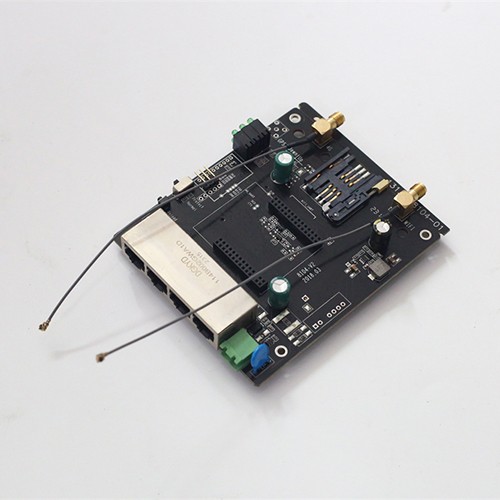
Communication gateway motherboard
- In the factory, the communication gateway motherboard can connect different types of production equipment, such as robots, CNC machine…
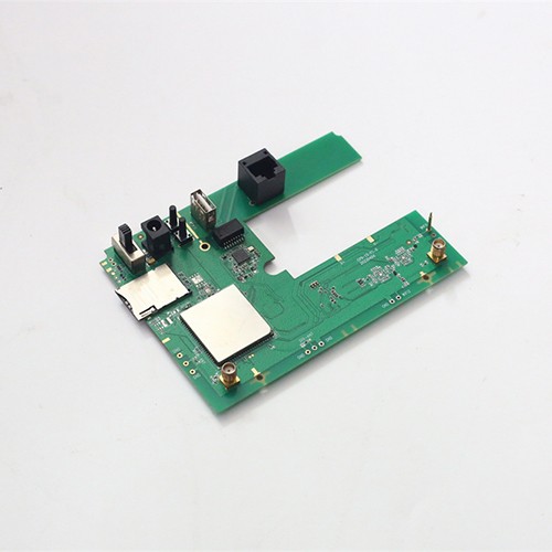
Four-port WIFI gateway
- A four-port WIFI gateway is a device with multiple network interfaces and wireless functions, usually used to connect different types of networks and realize communication and data transmission between networks.
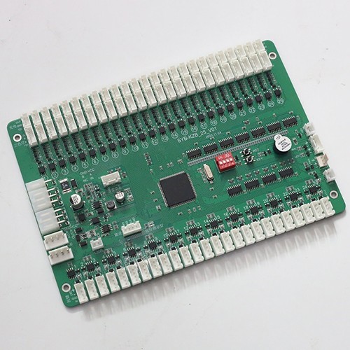
Internet of Things Fengchao Box Control Panel
- The IoT Fengchao box control panel is one of the core components of the Fengchao express cabinet, which is mainly responsible for controlling the various operations and functions of the express cabinet.
IoT and Connected Device PCBA
A connected device is usually a small board with an ambitious job: measure something, keep a radio link alive, and run for months or years on a battery. None of those three are decided by assembly alone, but all three can be damaged by it, and the damage is often invisible at test.
What connected device assembly involves
- Fine-pitch placement for radio modules and chipsets, with components from 01005 upward at pitches down to 0.25 mm.
- Antenna provisions respected as a specification: keep-out areas, ground via placement around the RF section, and the sequence of fitting a shield can relative to reflow.
- Thermal profiles set for the whole board where the design carries a cell or a temperature-sensitive sensor.
- Conformal coating where the product is installed outdoors or in a humid environment, with masking for connectors, test points and the antenna area.
- Test specified from the product function: power-up, radio link, sensor reading and, where relevant, current consumption.
Where radio performance is lost
Most RF problems in a production build come from three places, and none of them is the radio itself. The first is the keep-out area under or around the antenna, which is easy to violate with a test point, a screw boss or a coating layer applied over the wrong region. The second is grounding: the quality of the reference plane and the density of stitching vias around the RF section determine how much of the transmitter energy goes into the antenna and how much goes elsewhere. The third is assembly sequence and heat: a shield can fitted before reflow changes the thermal profile, and a module reflowed outside its floor-life window may fail intermittently rather than immediately, which is far harder to find.
Low-power design and the assembly process
Battery life is set by the design, but a few assembly decisions touch it. Flux residue on a high-impedance sensor input creates leakage that can dominate a sleep current; a marginal joint that adds resistance in the power path wastes energy continuously; and a cell exposed to more heat than it should withstand loses capacity from the first day. Cleanliness control, appropriate profile selection and careful handling of the cell are therefore part of protecting the design rather than extras.
From prototype to production
Connected products typically start small and then ramp once the design is stable. Because there is no fixed minimum order quantity and prototype and production builds use the same lines and process route, a design does not have to be requalified as it scales, and long-lead parts can be reserved against forecast once the ramp is planned. Send the Gerber files, the bill of materials, the module reference layout if one exists, and the quantity. Where the design also carries a shielded RF section, the assembly questions are shared with RF PCBA assembly.
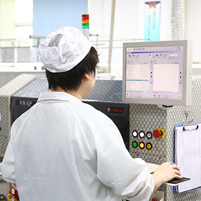
- Factory environment
What a connected device needs from assembly
Connected device boards: sensor nodes, gateways, metering and smart home controllers, assembled with fine-pitch radio modules, antenna provisions and low-power design in mind, from prototype builds through to volume production.
Where connected devices are deployed
Each application area has its own assembly requirements. What changes from a medical instrument to a motor drive is the process, the acceptance class and the design rules that matter, and the pages below set out what is different about each one.