

LED driver PCBA regulates the current that reaches an LED string and protects it from over-voltage, over-temperature and short circuits. Kilandu builds constant-current drivers with proper thermal management, RoHS-compliant materials and 100% functional test for architectural, industrial and automotive lighting makers.
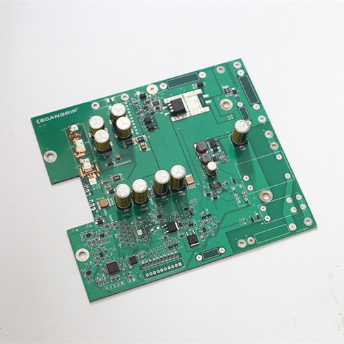
- Buck, boost and linear constant-current drivers
- Single or multi-channel, up to 10 A per channel
- OVP, OTP and short-circuit protection
- Thermal design for enclosed luminaires
- 100% functional test + aging
Capability
What Kilandu can build, test and ship for this product family.
| Parameter | Capability |
|---|---|
| Topology | buck / boost / linear |
| Current | up to 10 A per channel |
| Channels | 1-N |
| Protection | OVP / OTP / short-circuit |
| Test | 100% functional + aging |
| Lead time | 2-5 weeks |
Applications
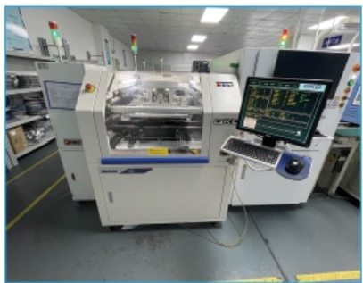
Lighting driver boards we have built - open one to see the board.
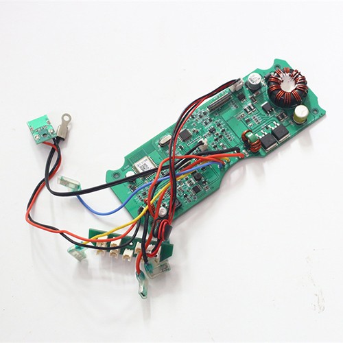
Special lighting power drive system
Multi-channel driver with over-voltage and short-circuit protection, built as a constant-current board with thermal relief for a sealed luminaire. 100% functional and aging tested before shipment.
View details →How we build it
From solder paste to tested board, inside our own factory in Shenzhen.
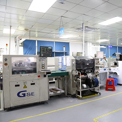
SMT assembly
01005 chips up to BGA and QFN placed on our high-speed SMT lines and reflowed with lead-free paste.
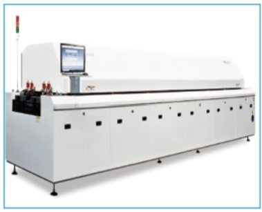
Reflow and wave soldering
Lead-free reflow for SMT, plus our DIP lines with lead-free wave soldering for the through-hole parts.
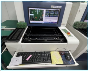
SPI, AOI, X-ray and ICT
3D SPI verifies solder paste volume before placement, AOI inspects every board after reflow, X-ray covers BGA and hidden joints, and in-circuit test runs on fixtures built to your netlist.

100% functional and aging test
Every driver board is functionally tested against your current and voltage targets, with aging or burn-in available before shipment.
What decides whether an LED driver board survives
A driver is judged by two things that pull in opposite directions: how tightly it holds its output current, and how much heat and electrical stress it can take while doing it. The topology sets the first. A buck, boost or buck-boost converter running in constant-current mode, or a linear regulator where the current is small enough to dissipate, each has its own sensitivity to layout: the current-sense return, the switching loop area and the placement of the inductor decide the ripple the LEDs actually see. The second is decided by the board itself - copper weight and copper area under the switching device, thermal vias into an internal plane, and in higher-power luminaires a metal-core or IMS substrate that carries heat into the housing.
Isolated or non-isolated: the safety margins change
Whether the driver is isolated from the mains decides what has to be held on the board. A non-isolated design shares a reference with the line, so creepage and clearance to any touchable part are set by the working voltage and by the pollution degree of the environment the luminaire is installed in. An isolated design adds a transformer or an isolated topology, which brings its own constraints: the barrier has to be maintained through assembly, and no coating, flux residue or stray solder may bridge it. Mains-connected luminaires are usually required to meet a safety standard such as UL or VDE / EN 61347 and an EMC standard, and the board layout - not only the bill of materials - is part of how those are met.
Materials, copper and potting
Higher-power and outdoor luminaires push the board into materials that FR-4 alone does not cover. Copper weights from 1.5 oz up to 3 oz and above carry the current and spread the heat; high Tg laminate keeps the board dimensionally stable when the driver runs hot for years; aluminium-backed IMS and metal-core boards move heat into the fixture rather than into the air inside it. Where the board has to survive moisture, condensation or vibration - street lighting, industrial and outdoor fixtures - a potting or conformal coating step is added, and the areas that must stay clear of it (connectors, test points, the isolation barrier) are defined before the process is set.
What is tested, and how inrush and surge are handled
Protection against inrush current and surge is verified as part of the board's function rather than assumed from the schematic: every board goes through AOI and in-circuit test, and a functional test at board level covers output current, protection behaviour and start-up. Aging or burn-in runs at temperature are used where the product warrants them. Lead times follow the usual pattern - prototype 5-8 working days, production 2-5 weeks - and a quotation is prepared from the Gerber, BOM and pick-and-place data, together with the mains voltage, the output current and any safety standard the luminaire has to meet.
Frequently Asked Questions
Quick answers to what buyers ask us most about this product family.
What LED driver topologies do you support?
Buck, boost, and linear constant-current drivers, single or multi-channel up to 10 A.
Do you test every LED driver board?
Yes - 100% functional test plus optional aging/burn-in before shipment.
Can you design the driver for my LED specs?
Yes - we provide NPI/engineering support to match current, voltage, and thermal requirements.
How is thermal performance handled on driver boards?
Driver lifetime is usually set by the temperature of the electrolytic capacitors and the switching device rather than by the LED itself. Thermal layout is reviewed at DFM stage: copper area and thermal via arrays under the hot devices, spacing between heat-generating parts, and where the stack-up allows it, metal-core or thick-copper construction to move heat into the enclosure.
Do you support metal-core and IMS boards?
Yes. Where the customer design calls for an aluminium or metal-core substrate for thermal reasons, fabrication and assembly are quoted as part of the turnkey build rather than subcontracted. The assembly profile for a metal-core board is developed per product.
What about protection circuitry and surge requirements?
Protection against over-voltage, over-temperature and output short circuit is normally designed into the driver by the customer, and our role is to assemble and inspect it to the acceptance class agreed. Where a build includes a gas tube or varistor for surge protection, the solderability and placement of those parts is reviewed at DFM stage.
Send us your Gerber and BOM
We will come back with a turnkey quotation - PCB, components, assembly and test - usually within one working day.