
Number of Layers: Two-layer
Dimensions: Approximately 120mm × 65mm
Surface Finish: Lead-Free Hydraulic Aluminum Stainless Steel (HASL)
Base Material: FR-4 with Green Solder Mask
Assembly Method: SMT + DIP
I. Product Features:
Microcontroller Core
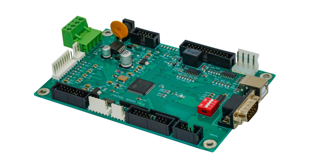
A QFP-packaged microcontroller/MCU is located in the center of the board, serving as the main control chip, responsible for logic processing and peripheral management.
Comprehensive Interface Expansion
Multiple black pin headers/sockets are located on the board to support external modules or signal input and output.
An RS232 port (DB9 connector in the lower right corner) is included for easy communication with a host computer or external devices.
A USB port (on the right) provides data transmission and power.
Power Management Circuit
The green terminal block, filter inductor, and electrolytic capacitor in the upper left corner indicate an independent power input, possibly supporting 12V or 24V input.
A power regulator chip is included on the board to provide power to the main control and peripherals.
Programmable Function Selection
The red DIP switch (bottom right) can be used to set the operating mode, address, or communication baud rate.
Signal Isolation and Protection
The board includes an optocoupler/driver chip area for isolating input/output signals and improving system security.
II. Application Scenarios:
Industrial Automation Controllers
Motor/Stepper Motor Drive Control Boards
Mechatronic Equipment (such as CNC Machine Tool Control Units)
Main Control Boards for Smart Terminals (Access Control, Time Attendance, etc.)
Control Core Modules for Medical Equipment or Laboratory Instruments
Various Test Equipment, Data Acquisition Systems
Number of Layers: Two-layer
Dimensions: Approximately 120mm × 65mm
Surface Finish: Lead-Free Hydraulic Aluminum Stainless Steel (HASL)
Base Material: FR-4 with Green Solder Mask
Assembly Method: SMT + DIP
I. Product Features:
Microcontroller Core
A QFP-packaged microcontroller/MCU is located in the center of the board, serving as the main control chip, responsible for logic processing and peripheral management.
Comprehensive Interface Expansion
Multiple black pin headers/sockets are located on the board to support external modules or signal input and output.
An RS232 port (DB9 connector in the lower right corner) is included for easy communication with a host computer or external devices.
A USB port (on the right) provides data transmission and power.
Power Management Circuit
The green terminal block, filter inductor, and electrolytic capacitor in the upper left corner indicate an independent power input, possibly supporting 12V or 24V input.
A power regulator chip is included on the board to provide power to the main control and peripherals.
Programmable Function Selection
The red DIP switch (bottom right) can be used to set the operating mode, address, or communication baud rate.
Signal Isolation and Protection
The board includes an optocoupler/driver chip area for isolating input/output signals and improving system security.
II. Application Scenarios:
Industrial Automation Controllers
Motor/Stepper Motor Drive Control Boards
Mechatronic Equipment (such as CNC Machine Tool Control Units)
Main Control Boards for Smart Terminals (Access Control, Time Attendance, etc.)
Control Core Modules for Medical Equipment or Laboratory Instruments
Various Test Equipment, Data Acquisition Systems