

VFD and frequency conversion PCBA covers the control, drive and I/O boards inside variable frequency drives, motor controllers, soft starters and industrial drive units. Kilandu builds these assemblies turnkey in Bao'an, Shenzhen, combining SMT, automatic DIP and lead-free wave soldering under a certified quality system with IPC-A-610 Class 2/3 acceptance.
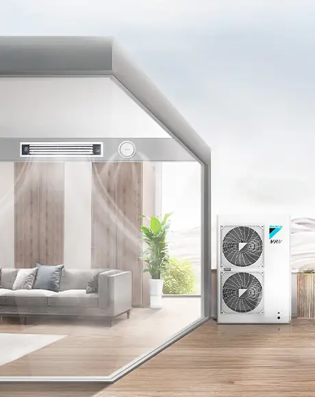
- Control, drive and I/O boards for VFDs
- Mixed SMT and heavy through-hole assembly
- Prototype to volume on the same lines
- Functional test against your drive specification
- IPC-A-610 Class 2/3
- RoHS / REACH compliant
- 2-5 weeks lead time
Capability
What Kilandu can build, test and ship for this product family.
| Parameter | Capability |
|---|---|
| Focus | Mixed-technology SMT plus through-hole assembly for drive boards |
| Service | Turnkey PCBA - component sourcing, SMT, DIP, assembly and test |
| SMT lines | High-speed SMT lines; equipment and monthly capacity are listed on the factory capabilities page |
| DIP lines | automatic DIP lines with lead-free wave soldering |
| Inspection | AOI, X-ray for BGA and functional test on customer-specific fixtures |
| Quality | Certified quality system with IPC-A-610 Class 2/3 acceptance criteria |
| Compliance | RoHS / REACH compliant processes, declarations on request |
| Records | Traceable inspection records issued with every batch |
| Lead time | 2-5 weeks after BOM and Gerber confirmation |
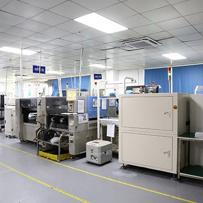
Applications
The drive applications these boards end up in.
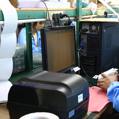
- 01
Industrial automation
Drive boards for production lines, textile machinery, conveyor control and CNC machine tools, where motor speed is adjusted to optimise the process.
- 02
HVAC systems
Fan and pump drives that hold precise temperature control while cutting energy use.
- 03
Pump and fan control
Water treatment, heating and air-conditioning drives that adapt flow and pressure to demand.
- 04
Elevators and hoists
Motor drive boards that keep acceleration smooth while reducing energy consumption.
- 05
New energy and wind power
Generator-side drive control that improves generation efficiency and stability.
- 06
Mining, metallurgy and heavy industry
Start, accelerate, decelerate and stop control for large motors, where reliability matters more than size.
How we build it
From solder paste to tested board, inside our own factory in Bao'an, Shenzhen.
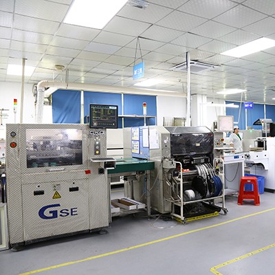
SMT assembly
01005 chips up to BGA and QFN placed on automatic high-speed SMT lines and reflowed with lead-free paste.
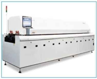
Reflow and wave soldering
Lead-free reflow for SMT, plus automatic DIP lines with lead-free wave soldering for the through-hole parts.
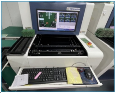
AOI, X-ray and ICT
Automated optical inspection on every board, X-ray for BGA and hidden joints, and in-circuit test on fixtures built to your netlist.
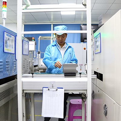
Functional test and traceability
Functional test against your own specification, with traceable inspection records issued for every batch.
Frequently Asked Questions
Quick answers to what buyers ask us most about this product family.
Can you assemble drive boards that mix SMT and through-hole parts?
Yes. A drive board normally pairs fine-pitch SMT logic with heavy through-hole power devices, so it runs through the same factory: high-speed SMT lines and automatic DIP lines with lead-free wave soldering, then AOI and functional test before packing.
Do you support both prototype and volume runs of the same board?
Yes. Most drive projects start with prototype or pilot quantities to validate the design and our process, then ramp to volume on the same high-speed SMT lines and automatic DIP lines, so the process, materials and test method stay unchanged between the two stages.
Which standards apply to VFD and frequency conversion PCBA?
Orders run through a certified quality system with IPC-A-610 Class 2/3 acceptance criteria, and processes are RoHS and REACH compliant. Traceable inspection records are issued with every batch.
What is the lead time for frequency conversion boards?
For most drive assemblies, 2 to 5 weeks from the point the BOM and Gerber are confirmed and components are released, depending on material lead times for power semiconductors and whether test fixtures have to be built first.
Send us your Gerber and BOM
We will come back with a turnkey quotation - PCB, components, assembly and test - usually within one working day.