

The cabin motherboard is the carrier that ties the modules of an intelligent cabin together: it distributes power, routes the high-speed display and camera links, and provides the connector field that the sub-assemblies plug into.
What this board typically includes
- A multi-layer stack-up with controlled-impedance routing for display and camera links.
- Power distribution with multiple regulated rails and inrush limiting.
- Board-to-board and wire-to-board connector fields.
- Mounting and shielding provisions for EMC control.
How Kilandu builds and tests it
Multi-layer boards are assembled on the same high-speed SMT lines used for our other automotive work, with reflow profiling recorded per work order. X-ray inspection covers BGA and other joints that cannot be seen optically, and functional test can be run to your specification. Kilandu holds IATF 16949:2016, ISO 9001:2015 and ISO 14001:2015, and works to IPC-A-610 Class 2 and Class 3 acceptance criteria.
Why the stack-up decision comes first
A cabin motherboard is usually the largest single board in the vehicle interior and the one with the widest mix of signals on it. High-speed differential pairs for camera and display run alongside switching regulators and a connector field that carries the full system current. Each of those needs a reference plane, and there are never quite enough layers to give every one of them an undisturbed return path.
The practical answer is to fix the stack-up against the signal and power requirements before layout starts, decide which nets get a dedicated reference plane and which can share one, and treat copper weight as a thermal and current-carrying decision rather than a default. Changing layer count or copper weight later changes impedance, and impedance changes mean the design has to be re-simulated and the bare board re-qualified.
Fabrication and assembly in one supply chain
Because Kilandu runs fabrication and assembly together, panelisation, fiducial placement, surface finish and tooling holes are planned around the SMT and DIP process rather than inherited from a separate supplier. The plant operates high-speed SMT lines and automatic DIP lines with capacity documented on the factory capabilities page, materials are RoHS and REACH compliant, and production records are retained per lot. Typical turnkey lead time is 2 to 5 weeks.
-
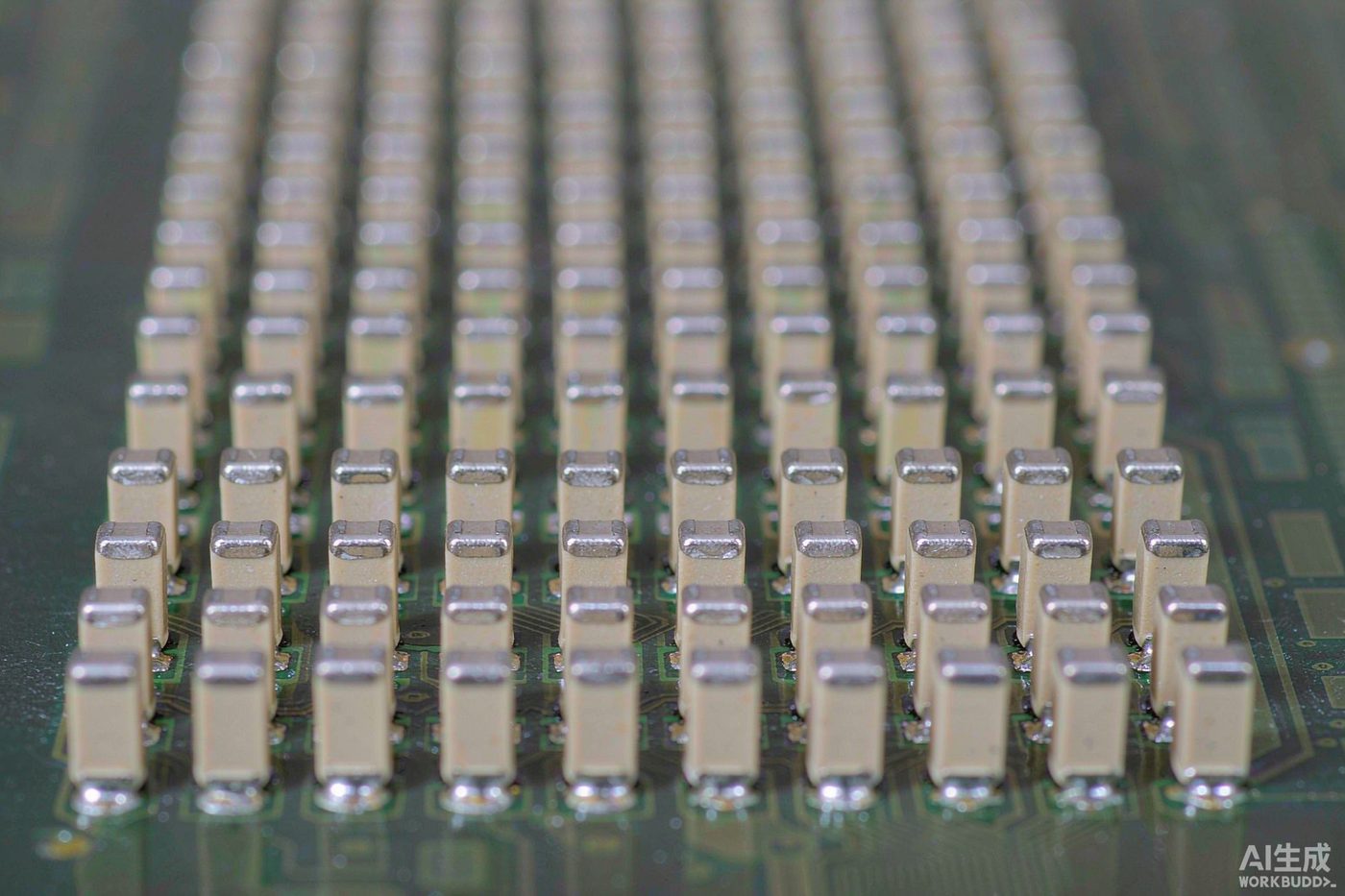
Passive Component Lead Times Are Rewriting PCBA Sourcing Decisions in 2026
-

A warm welcome to Mr. Jason Connor and Mr. David from Luxembourg for their guidance!
-

The PCBA Industry at the Start of 2026: AI Drives Market Surge, Intelligent Manufacturing and Material Upgrades Become the Main Themes
-
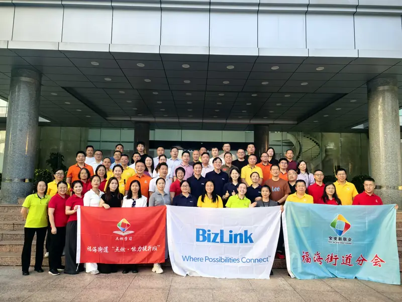
Connecting Infinite Possibilities | Bao'an District New Union 'Ignite Learning' Class (including our Shenzhen Jintianlei Innovation Technology Co., Ltd.) visited Biz Link to discuss new development op
-
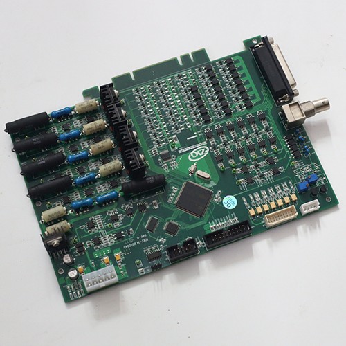
The core process of PCBA product customization
-
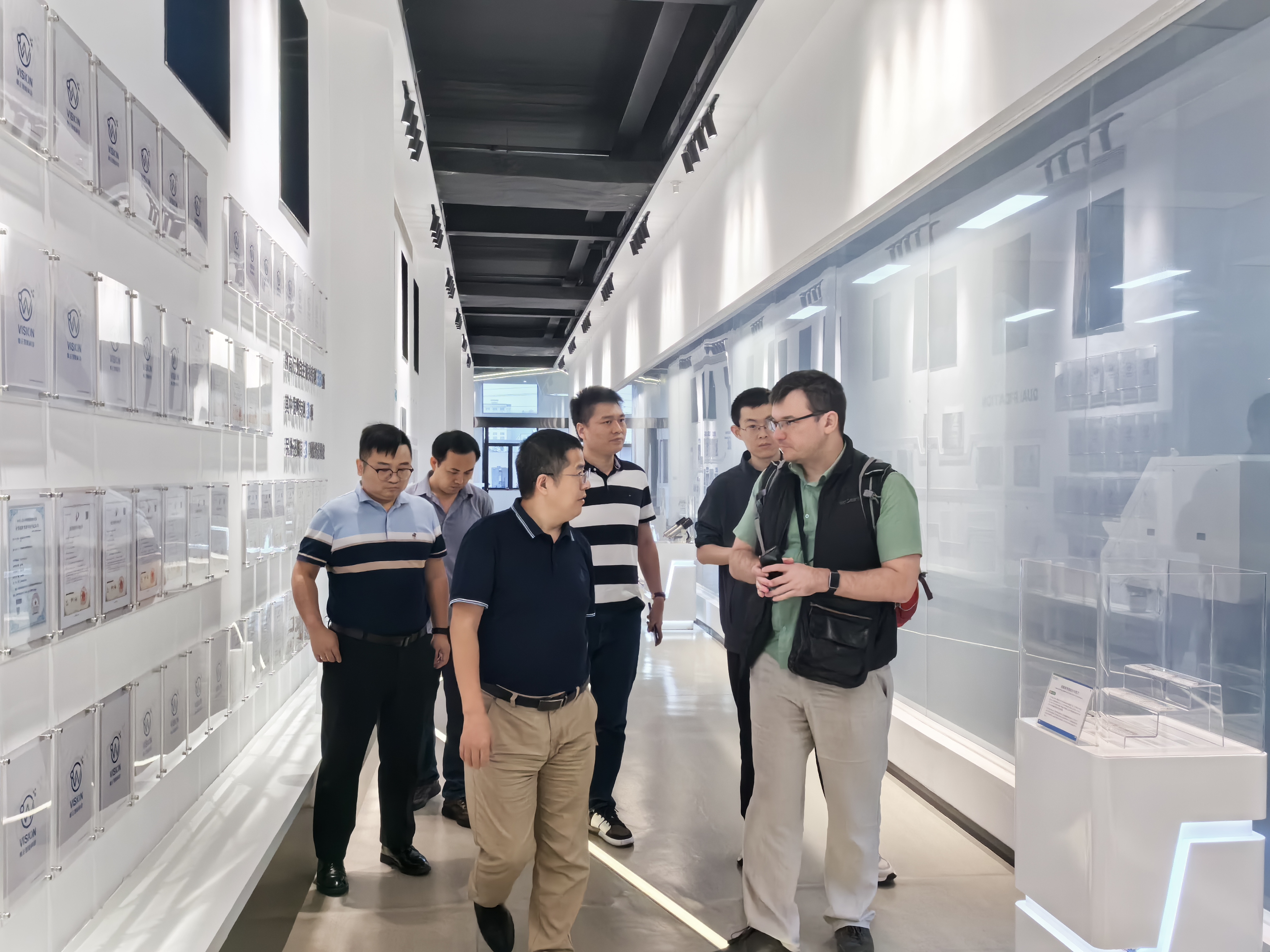
Welcome customers to visit our branch companies for factory inspection and guidance
-
ExpeElectronica2024 in Munich, Germany
-
PCBA industry global prospects
-
Connecting Infinite Possibilities | Bao'an District New Union 'Ignite Learning' Class (including our Shenzhen Jintianlei Innovation Technology Co., Ltd.) visited Biz Link to discuss new development op
-
Explore the future trends of the PCBA industry! How can you make your production line more efficient with the help of intelligent technology?