

When an MLCC becomes difficult to source, finding another part with the same capacitance and package size can look like the quickest fix. It is not always the right one.
Two capacitors may carry the same nominal value and voltage rating but deliver different capacitance once they are installed in a working circuit. That matters particularly with X5R and X7R ceramic capacitors, whose capacitance can fall under DC bias. The size of that reduction varies by part and manufacturer.
A replacement can therefore pass a basic incoming check and still behave differently on the board. Before approving a second source, compare the parts under the conditions they will actually face.
Why matching part numbers on paper is not enough
X5R and X7R are Class 2 ceramic dielectrics. When DC voltage is applied, their effective capacitance can decrease. The value printed on the part or datasheet is measured under specified test conditions; it does not necessarily represent the capacitance available at the circuit's operating voltage.
For example, published technical guidance describes cases where a 10 µF MLCC delivers roughly 4–6 µF at its rated DC voltage. The actual result depends on factors such as package size, voltage rating and the manufacturer's dielectric formulation. Two parts marked 10 µF should therefore be treated as candidates for comparison, not automatically as equivalents.
Temperature can add another variable. A DC-bias curve measured at 25 °C does not, by itself, tell you how much capacitance will remain when the component is operating at a higher temperature. If the board regularly runs above 60 °C, check the relevant temperature characteristics as well as the bias curve.
The cost of choosing without the data
When the bias information is missing, buyers may compensate by choosing a higher capacitance or voltage rating. For instance, a 10 µF, 10 V X7R in an 0805 package might deliver around 5 µF at 5 V. A 22 µF, 16 V part in a 1206 package may be considered to recover the required effective capacitance. That change can raise the component cost and take up more board space.
The electrical consequences depend on the circuit. In a buck converter's input-decoupling network, for example, a capacitor that falls from 10 µF nominal to 4 µF under 12 V bias can affect input ripple and loop behaviour. Measuring the removed part at zero bias may still show a value close to 10 µF, so a simple bench check may not reproduce the condition that caused the problem.
Variation between production lots also deserves attention. DC-bias performance depends on the ceramic formulation and manufacturing process, and published guidance suggests two lots from the same manufacturer can differ by around 5–8 percentage points at the same bias point. If a design has little margin, a difference of that size is enough to push some units outside the intended range. Ask for the relevant data rather than assuming that all parts with the same headline specification will behave alike.
Six checks for a proposed replacement
A second-source review should cover more than capacitance, voltage and package size. These six checks provide a practical starting point.
1. Dielectric and temperature rating
X7R is rated for operation up to 125 °C, while X5R is rated up to 85 °C. An X7R-to-X5R substitution may be suitable only if the design's worst-case temperature, including self-heating, remains within the replacement's rating and the design requirements. Replacing C0G with a Class 2 dielectric is not a like-for-like change in timing, filtering or RF applications.
2. Capacitance at the actual DC voltage
Compare the manufacturers' DC-bias curves at the voltage across the capacitor in the circuit. Do not compare only the nominal values or read the curves at the capacitor's maximum rated voltage unless that is also the application voltage.
3. Voltage rating
A higher voltage rating can improve effective capacitance, particularly when the package size is unchanged. Moving from 6.3 V to 10 V or 16 V may be worth evaluating. A lower rating is different: it should not be accepted as a purchasing-only decision and needs engineering review against the design's derating rules.
4. Package dimensions and thickness
The case code normally identifies length and width, but thickness can vary. Check the full part number and mechanical drawing, especially where a shield, enclosure or pick-and-place setup leaves little clearance.
5. Qualification grade
A component's qualification grade must suit the product and its approval requirements. An automotive-grade part may be usable in a commercial design, but replacing a qualified automotive component with a commercial-grade part may require engineering approval and, depending on the programme, customer approval.
6. Termination and packaging
Soft or flexible terminations can reduce the risk of cracking caused by board flex, particularly near connectors and board edges. Do not remove that feature from the design without considering the mechanical risk.
Also check the ordering suffix: reel packaging and cut tape may be listed as different orderable part numbers.
A supplier cross-reference is useful for identifying candidates. It is not, by itself, approval to substitute the component. The final decision belongs to the team responsible for the design.
A quick screening rule — not an approval criterion
If a manufacturer's bias curve is not immediately available, the ratio of applied voltage to rated voltage can help prioritise which candidates to investigate. As a rough screening guide, parts operated at no more than half their rated voltage may retain a larger share of nominal capacitance than parts operated close to their rating. Some published guidance gives indicative ranges of 85–95% retained at half-rated voltage and 50–70% near the rated voltage.
These are only screening estimates. They vary with the part, package and dielectric formulation, so they should never replace the manufacturer's data or an engineering acceptance limit.
For example, if a 16 V part operates at 6.3 V, a retained-capacitance ratio below 0.85 is a reason to investigate the actual curve. If a 10 V part operates at 9 V, a ratio around 0.6 may be plausible — but the important question is whether the original design allowed for that reduction.
Compare under the same conditions
Before comparing two candidates, make sure the data uses comparable conditions:
- DC bias: Use the voltage across the capacitor in the application. If the circuit rail is 6.3 V, request the value at 6.3 V even if the part is rated for 16 V.
- AC measurement level: Class 2 MLCCs are often measured at 1 kHz and 1 Vrms, although some manufacturers use 0.5 Vrms. Record the conditions and keep them consistent when comparing data.
- Temperature and data type: Note the temperature at which the curve was measured, often 25 °C. Check whether the curve is typical, simulated or guaranteed; those labels do not mean the same thing.
Pay attention to the graph's vertical axis, too. A 40% decrease means 60% remains. It does not mean the capacitor retains only 40%. Confusing "percentage loss" with "percentage retained" can lead to the wrong conclusion.
A higher voltage rating is not automatically the best choice for every circuit. If the applied voltage is low and the original part already retains most of its nominal capacitance, upgrading the rating may add cost without solving a real problem. The decision should follow the design requirement and the available data.
What should incoming inspection check?
After engineering approves an alternate, the incoming inspection plan should reflect the component's intended use. Depending on the application and the agreed specification, useful checks include:
| Parameter | Example test condition | Example acceptance approach |
|---|---|---|
| Nominal capacitance | 1 kHz, 1 Vrms | Within the datasheet tolerance, such as ±10% where specified |
| Effective capacitance under bias | 1 kHz, DC bias matching the application voltage | Compare with the approved supplier value and the design's minimum requirement |
| Capacitance ratio | Same measurement conditions, with and without DC bias | Record the actual ratio and review the available design margin |
| ESR under bias | 1 kHz with DC bias applied | Compare against the approved specification; do not assume a zero-bias value applies |
| Insulation resistance | At the specified temperature and test voltage | Use the component datasheet or approved inspection specification |
| Capacitance change with temperature | Across the application's required temperature range | Check against the dielectric specification and project requirements |
The numerical limits must come from the component datasheet, circuit requirements and approved inspection plan. A single generic threshold is not appropriate for every MLCC or application.
Where the supplier does not provide a DC-bias curve, the part may still be considered, but the missing information should be addressed explicitly. Engineering may require additional testing or define an incoming inspection method before the alternate is released for production.
Why second-source decisions matter for 2027 planning
Supply agreements and capacity investment announcements suggest that demand for some MLCC categories remains strong, particularly for AI-server applications. That does not mean every MLCC is in shortage, or that every buyer will face the same lead times. It does mean that teams relying on a single approved part should understand their alternatives before a supply problem becomes urgent.
A report published by China Powder Network on 10 October 2026, citing Korean media and Nikkei, described several relevant developments. Samsung Electro-Mechanics disclosed a contract valued at approximately KRW 285.61 billion for MLCCs used in AI-server hardware, covering deliveries from January through December 2027. The customer and the contract's component specifications were not disclosed.
The report also described investment by Okayama Murata Manufacturing in ceramic raw-material production lines, with construction scheduled to begin in October 2026 and production expected from April 2028. Murata had separately outlined an investment plan for MLCC production equipment, targeting additional capacity by fiscal 2027.
These announcements provide context, not a forecast for every capacitor series. The practical lesson for procurement is narrower: if a part is important to a 2027 build, evaluate a second source while there is time to compare data, run tests and obtain approvals. Capacity announced for a later date does not solve an immediate sourcing issue.
A practical approval process
For a project that may need an alternate MLCC, work through the following steps:
- Start with the circuit requirement. Confirm what the capacitor does and what effective capacitance, voltage, temperature and ripple conditions the application requires. For regulator circuits, use the datasheet and revision for the exact device in the design.
- Record the operating conditions. Note the DC voltage across the capacitor, the temperature range and any relevant ripple or transient conditions. Input and output capacitors near the same regulator may operate under different conditions.
- Collect complete part information. Obtain the full ordering code, datasheets and available DC-bias curves for both the original and proposed part. Include packaging suffixes and record the document revision or retrieval date.
- Compare the evidence. Review effective capacitance at the application voltage, temperature rating, package dimensions, termination, qualification grade and packaging.
- Agree on acceptance criteria. Where a minimum effective capacitance is required, state it explicitly. For example, "10 µF nominal, at least 6.8 µF at 6.3 V under the specified measurement conditions" is more testable than a nominal value alone. The actual limit must be set by the design team.
- Document the decision. Record who approved the alternate, which data was reviewed, any test results and any customer approval required. This avoids repeating the same review when the next order is placed.
Kilandu's PCB DFM service covers manufacturability review, and its quality assurance process describes how inspection records are handled on the shop floor. For a PCBA project involving alternate components, send the BOM, approved vendor list and test requirements with the Gerber files. The team can then identify proposed alternates that need engineering review before the build is quoted or released.
Frequently asked questions
Can two MLCCs with the same nominal value be used interchangeably?
Not automatically. Matching capacitance, voltage rating, dielectric and package size is a starting point. For X5R and X7R parts, effective capacitance under DC bias can differ between manufacturers. The design team should compare the data under the application's actual conditions before approving the substitution.
What is DC bias, and why does it reduce capacitance?
DC bias is the effect an applied DC voltage has on a capacitor's effective capacitance. In Class 2 ceramic dielectrics such as X5R and X7R, capacitance generally falls as the applied voltage increases. Temperature can affect the result as well. C0G parts behave differently, so replacing C0G with a Class 2 dielectric needs particular care in timing, filtering and RF circuits.
How much capacitance can an MLCC lose under DC bias?
There is no single figure for every part. Published examples for 10 µF parts show values around 4–6 µF at rated DC voltage, but the result depends on the package, voltage rating and dielectric formulation. Use the manufacturer's curve for the exact part number when assessing a candidate.
What should incoming inspection test?
Start with nominal capacitance, effective capacitance at the application's DC bias, the ratio between biased and unbiased capacitance, ESR where relevant, and insulation resistance. Temperature-related capacitance change may also need to be checked. The exact conditions and limits should be taken from the datasheet and approved inspection plan.
Is a higher voltage rating always a safe replacement?
No. A higher rating can improve effective capacitance, but the part still needs to meet the design's electrical, mechanical and qualification requirements. It may also cost more or require a larger package. Compare the actual data instead of applying a blanket rule.
Can mechanical or thermal stress crack an MLCC?
Yes. MLCCs have brittle ceramic bodies, and board strain can cause cracks. Possible sources include PCB bending, depaneling, screw tightening, connector insertion, press-fit operations, thermal shock and rework. Flexible terminations can help in some applications, so confirm that the replacement retains any required mechanical protection.
How long should an alternate-component review take?
There is no fixed duration. A straightforward comparison may be quick when complete datasheets and bias curves are available. Testing, design changes and customer approvals can take longer, especially in automotive programmes. Starting the review before the original part becomes unavailable gives the team more time to make a documented decision.
Sources
China Powder Network, "MLCC 巨头:爆单、扩产停不下来!", 10 October 2026. Cited for the Samsung Electro-Mechanics AI-server MLCC contract of approximately KRW 285.61 billion covering January to December 2027 with the customer undisclosed, and for the Okayama Murata ceramic raw-material line scheduled to begin construction in October 2026 with production from April 2028.
https://news.cnpowder.com.cn/20261010/91769.html
AKKN Electronics, "DC-Bias Capacitance Drop in Class 2 MLCCs: Sourcing Checks Before Substitution", 11 September 2026. Cited for the DC-bias mechanism in Class 2 dielectrics, the published examples of 10 µF parts delivering around 4–6 µF at rated voltage, the indicative 85–95% and 50–70% retained-capacitance ranges, and the batch-to-batch variation figure of roughly 5–8 percentage points at the same bias point.
https://www.akkn.com/news/8427.html
GlobX, "MLCC Shortage 2026: Which Capacitors Are Hit and a 6-Point Substitution Check", 2026. Cited for the structure of the six-point substitution check and for the statement that matching nominal value and case code is not sufficient on its own.
https://globx.eu/blog/buyers-guides/mlcc-shortage-2026
CPlus Electronics, "MLCC DC Bias: How to Qualify a Replacement Capacitor", 2026. Cited for the guidance that acceptance criteria should follow the capacitor's function in the circuit and the datasheet revision of the exact device used, that input and output capacitors near the same regulator may operate under different conditions, and that a selection graph should not be treated as a production acceptance specification.
https://cpluselectronics.com/blog/mlcc-dc-bias-how-to-qualify-a-replacement-capacitor1791717650


-

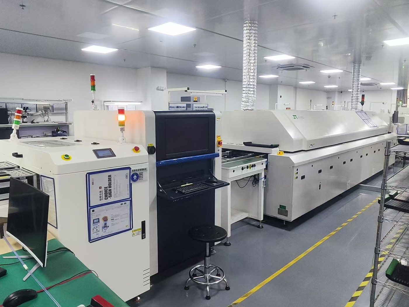
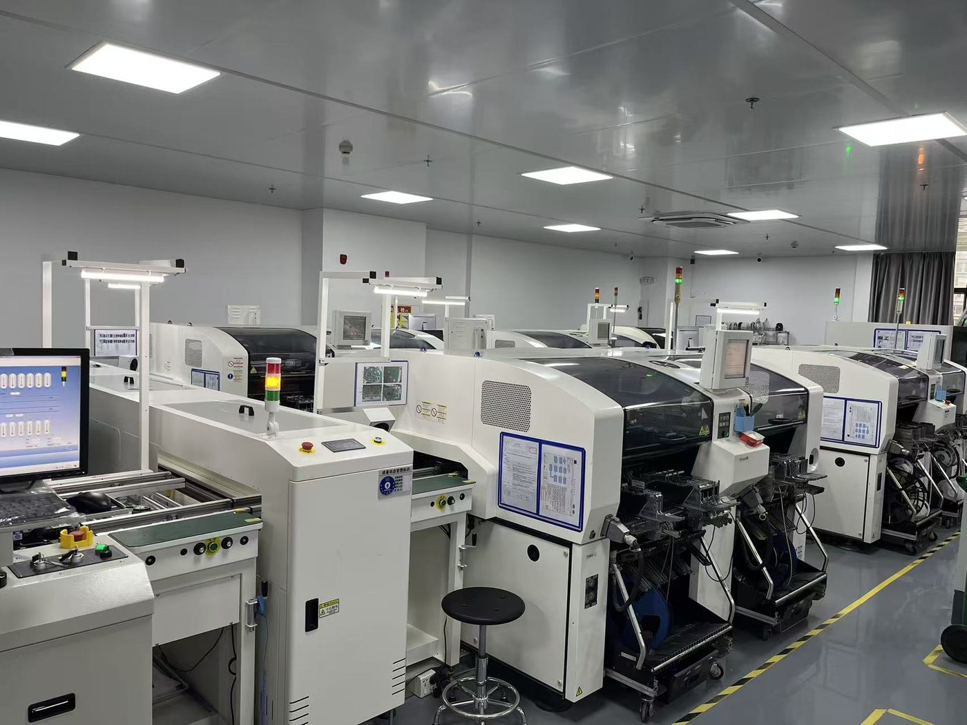
Welcome customers to visit our branch companies for factory inspection and guidance
-
ExpeElectronica2024 in Munich, Germany
-
PCBA industry global prospects
-

Connecting Infinite Possibilities | Bao'an District New Union 'Ignite Learning' Class (including our Shenzhen Jintianlei Innovation Technology Co., Ltd.) visited Biz Link to discuss new development op
-

Welcome French customer PACE to visit our factory for audit