
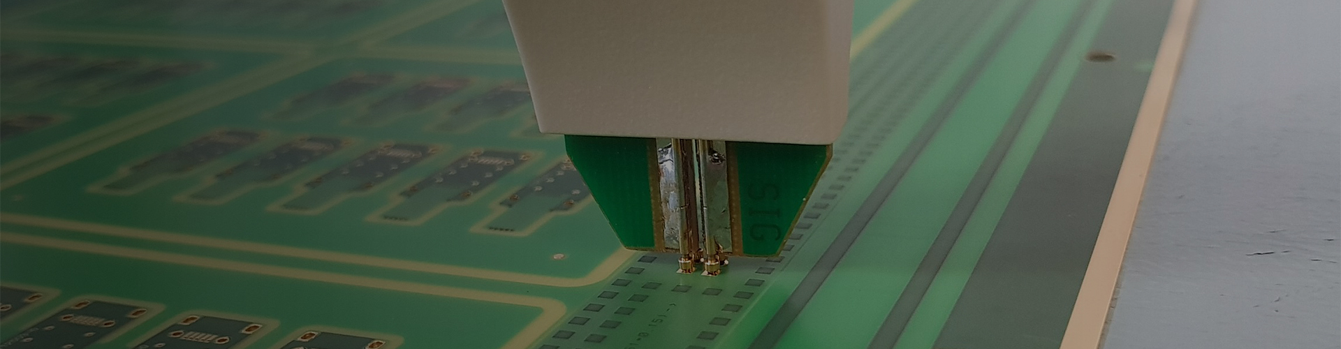
Short answer. No single test method is complete, so a useful test plan layers them. SPI checks the paste before any component is placed. AOI checks the joints visible from the surface. X-ray checks the joints hidden under a package body. ICT checks the board against the netlist without powering it. FCT checks that the assembly performs to specification. Each method has a blind spot, and the blind spots are the reason more than one is used.
What each method catches, and what it does not
- SPI - solder paste inspection. Catches paste volume, height and registration faults before any component is placed. It does not catch anything about component quality.
- AOI - automated optical inspection. Catches joint defects and placement errors visible from the surface. It does not catch joints hidden under a BGA or QFN body.
- X-ray. Catches hidden joints, including voiding and bridging under area-array packages. It does not tell you whether the circuit functions electrically.
- ICT - in-circuit test. Catches component presence, value and orientation against the netlist. It needs test access on the board, and it cannot confirm the circuit works in the application.
- FCT - functional test. Confirms the assembly performs to specification. It only covers the conditions and measurements the specification defines.
The first article is an approval gate
Before a programme moves into volume, the first assembly is treated as an approval gate rather than as one more build. It is inspected and tested to the full scope agreed at quotation rather than sampled, and the results are recorded against the design. Three things come out of that gate: the first article inspection report, which the customer's own quality system can file; the golden sample, the approved board retained as the reference for later builds; and the written approval, after which the process, the fixture and the material are frozen for the run. Nothing is released to volume before that result has been reviewed and approved in writing, which is what stops a process error from being repeated across a whole order.
Choosing the test scope for a programme
Scope is a decision, not a default. Fine-pitch and area-array work in particular benefits from combining SPI, AOI and X-ray. A board with no test points can be inspected and tested, but not in-circuit tested efficiently, and that is a design decision made before the layout is fixed. A programme that needs only a power-on check should say so, and a medical or automotive programme should say what it needs. Either way it should be written down at quotation, because the fixture and the programme cost follow the scope.
Fixtures and programme cost
Functional test runs on fixtures built to the customer's specification. The fixture and the programme are one-time items belonging to the programme, and they are quoted separately. On a small build they are often the largest single line in the quotation, which is worth knowing before the test scope is agreed rather than after.
Records
Programming and device configuration are recorded per unit where firmware is loaded. Inspection and test results are retained against the lot, and a failed unit goes through documented rework and retest rather than being passed. The lot records tie the assembly back to the material it was built from, which is what makes a field return diagnosable rather than a matter of opinion.
What Kilandu does
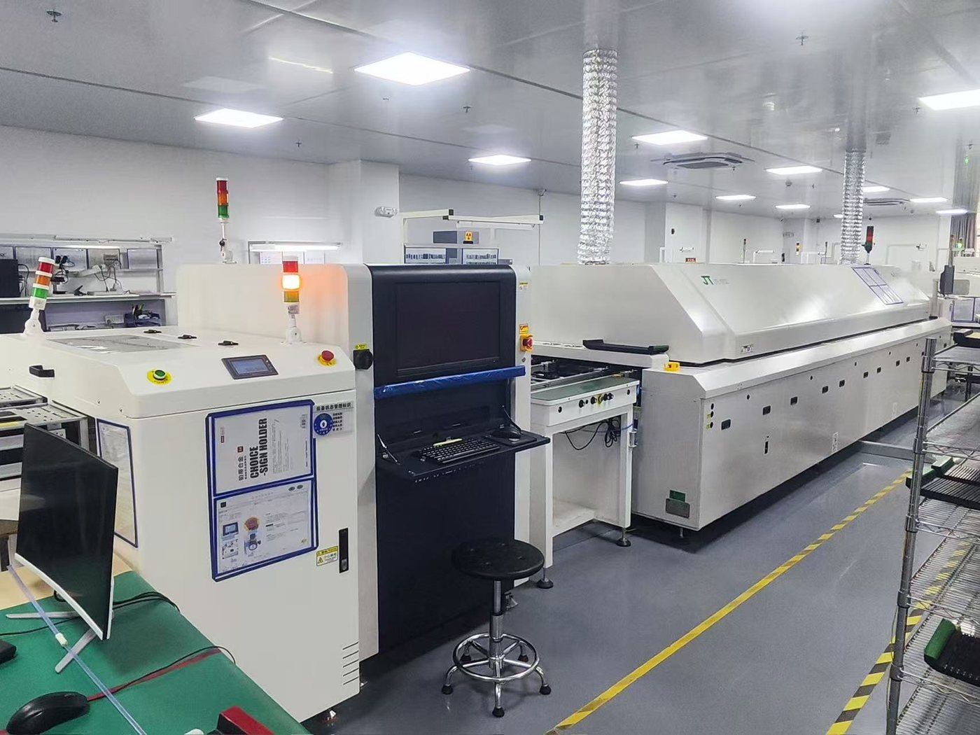
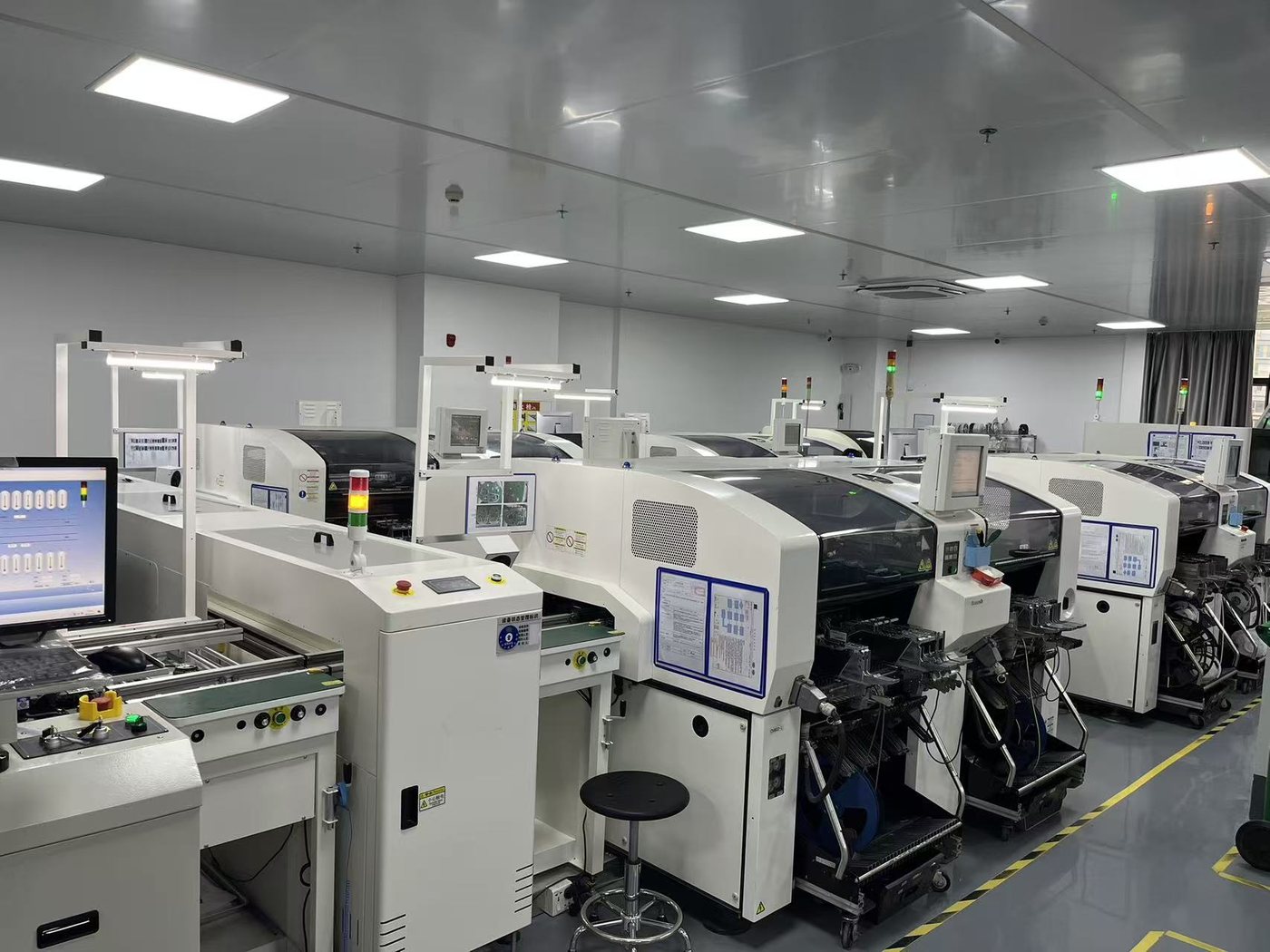
In-process inspection at Kilandu is SPI, AOI and X-ray; electrical test is ICT and FCT. The first article of a volume run is inspected to the full agreed scope rather than sampled, and the approved board is retained as the golden sample. The method-by-method detail is on the testing page, and the X-ray capability is described on the BGA and X-ray answer page. To agree a test scope, send the test specification to alden@kilandu.com.


-
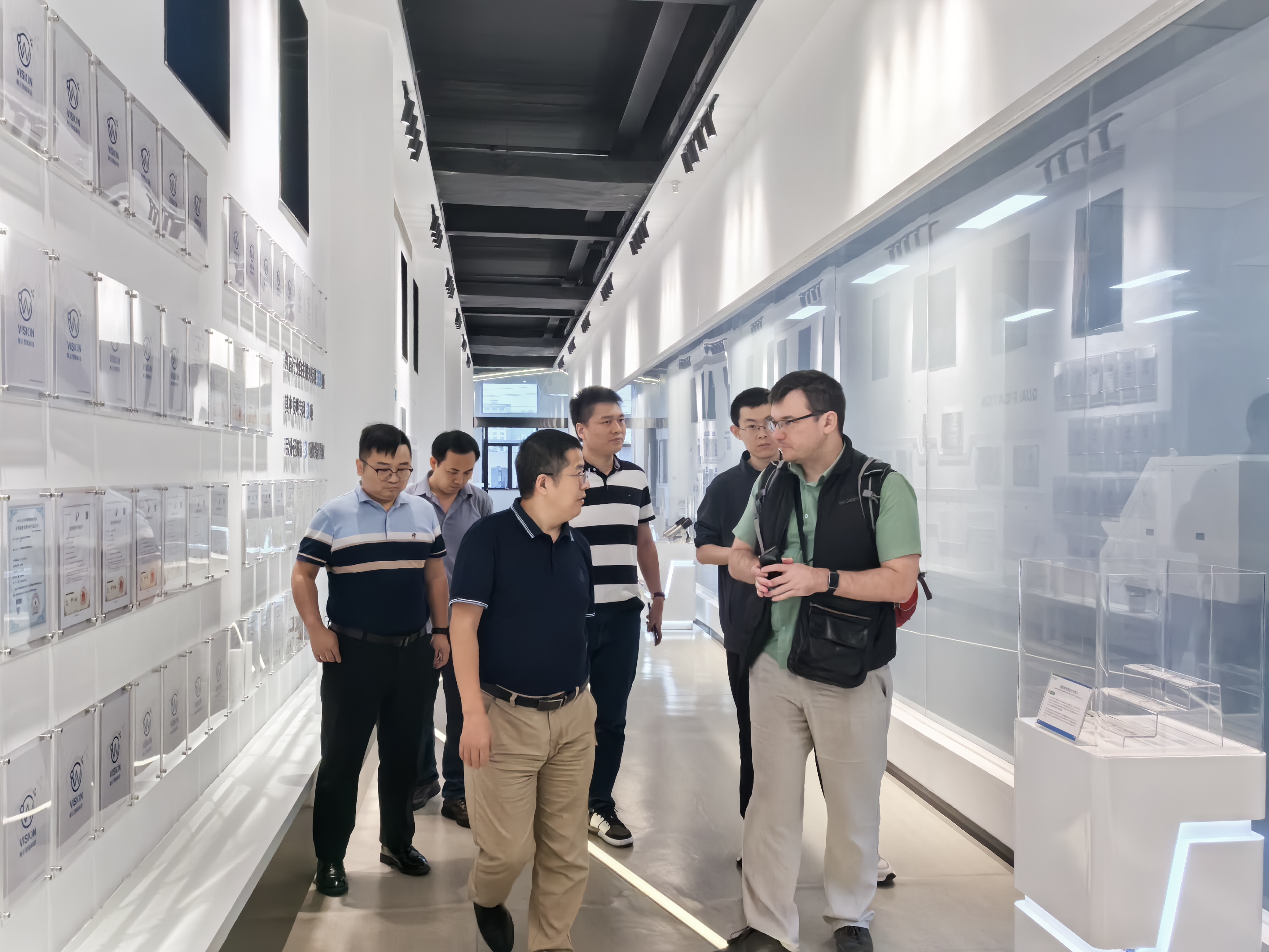
Welcome customers to visit our branch companies for factory inspection and guidance
-
ExpeElectronica2024 in Munich, Germany
-
Connecting Infinite Possibilities | Bao'an District New Union 'Ignite Learning' Class (including our Shenzhen Jintianlei Innovation Technology Co., Ltd.) visited Biz Link to discuss new
-
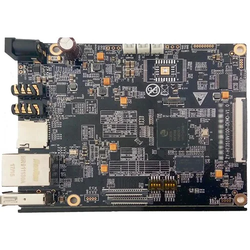
PCBA industry global prospects
-
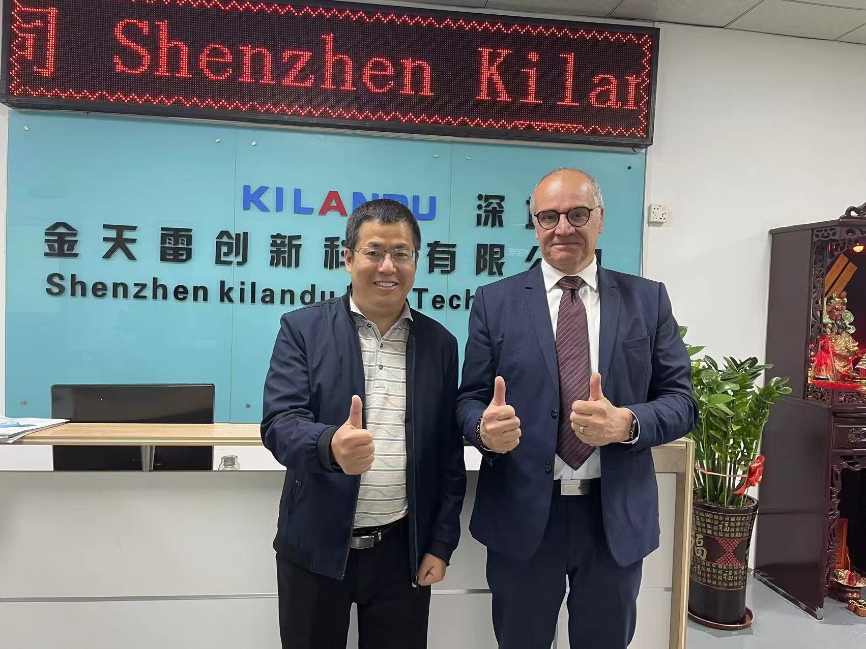
Welcome French customer PACE to visit our factory for audit